|
|
SWIFT Operations
Operating SWIFT is very straight-forward, as there are very few instrument parameters to set up. The spectrograph has a fixed spectral format, and as it is an IFS with a decent field size, one can typically just point-and-shoot. The pointing of the telescope is typically good enough for the target to be within the field of view at the largest spaxel scale.
Please refer to the operations manuals for detailed information. The points below cover some of the more common questions/unique-features of SWIFT.
Instrument Setup
There are very few things that need setting up before the start of observations:
- Choice of dichroic: There are two dichroics available for SWIFT, with separation wavelengths of 650 nm and 750 nm. All light at wavelengths longer than these values is sent to SWIFT, the shorter wavelength light is used for guiding and wavefront sensing by the AO. See the SWIFT AO Performance section on details on how the guide star limiting magnitudes need to be modified w.r.t. the PHARO numbers when using the SWIFT dichroics. Clearly, the 750 nm dichroic provides better AO performance, but should only be used if no feature shortward of 750 nm is of scientific interest. Dichroics can be changed by the instrument support astronomers (Kevin/Carolyn/Jamey), so it is hard to make a change of dichroic during the night.
- Spaxel scale: Choose the 0.080″/spaxel scale for observations where good AO correction is expected, and the 0.235″/spaxel scale for all seeing limited observing. The 0.016″/spaxel scale is primarily intended for use with PALM3K, operating close to the diffraction limit with very bright (V < 10) natural guide stars. Spaxel scale changes can be done on-the-fly, and take less than a minute to complete.
Target Acquisition
- Real Time Display: SWIFT provides an RTD (real time display) that can display reconstructed images a couple of seconds after the detectors have been read out. Although the reconstruction has slight imperfections, it is more than sufficient for acquisition and centering purposes.
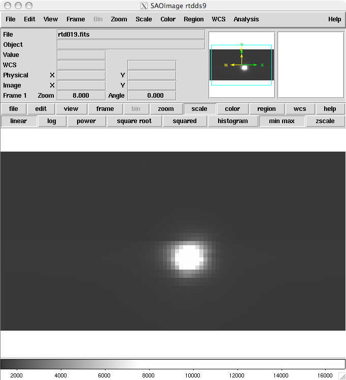
The RTD displays the entire field of view (both spectrographs) (see the User Manual for run-time options of the RTD). It also shows the orientation on the sky (yellow arrows in the preview window of DS9). The default Cassegrain rotator Position Angle (PA) of 100.9° orients the long axis of the field of view in the East-West direction. For other PA, use the formula Cass Rotator Angle = PA + 100.9°. The sense of rotation is such that the yellow arrow showing North rotates clockwise w.r.t. the field of view for positive increments of the Cass Rotator Angle.
- AO Flatmap: Even if the AO is not being used, the light path through SWIFT still goes through the AO system. However, the deformable mirror within the AO needs to be set to its nominal flat state to ensure that it does not degrade the telescope images. In fact, we can use the flatmap to advantage to improve the telescope PSF, by removing any static aberrations within the system (e.g. focus of the telescope, astigmatism). This procedure needs to be carried out by the AO operator prior to commencing non-AO observations, and takes about 10 mins to execute. It should be repeated at least every couple of hours, and possibly every hour, as the telescope focus has been observed to drift on that time scale in a way that visibly affects the PSF (this is particularly true at the start of night, or if the temperature is changing quickly).
- Acquisition of faint targets: For targets that cannot be seen in a reconstructed image of an exposure lasting 120 seconds or less, it is wise to make a blind offset from a nearby star or galaxy to ensure accurate positioning of the target within the field of view. The offset star observations can also be used to estimate the seeing. In addition, the off-axis SWIFT guider can be used to ensure accurate re-acquisition and tracking (though note that residual flexure limits it's usefulness on separate sides of the sky!). For AO assisted observations, the AO reference star can always be used as the PSF reference.
- Acquisition Overheads: Apart from the overheads involved in
achieving AO loop closure on the desired target, there should be only a few
minute additional overhead for target acquisition and positioning within the
field of view. Detector read-out time is ≈ 150 seconds for slow (science) readouts, and ≈20 seconds for fast (acquisition) readouts. SWIFT
is equipped with a shutter to control short exposure times.
- Flexure: SWIFT suffers from some gravity induced flexures (probably from the CCD mounts) as the telescope tracks across the sky. Depending on target position and instrument rotation, this can be at a rate of up-to ~1 pixel/hour. The data reduction pipeline copes well with this for 'typical' exposures in the 235mas scale, using the OH sky lines to track and correct the flexure. In the smaller scales, or for short exposures, an open-loop model of the flexure exists which can be used. Contact the instrument team if this is of interest to you. It is, if you can afford the time, worth taking calibration exposures (arcs + VL) with the telescope in the same position as the observations (every 1--2 hours in HA). Using these specific calibrations rather than those taken at zenith minimises the effects of flexure.
Long Exposures
- Guiding for non-AO observations: It has been noticed that without any secondary guiding, the telescope drifts by 1 to 2 arcsec within 15 to 30 minutes. This can significantly worsen the image quality achieved in long exposures, especially under good seeing conditions. It is highly recommended to operate a slow guiding loop using the off-axis SWIFT guider.
- Limitations of cosmic rays: We expect individual exposure times to be
restricted to 1800 secs due to the number of cosmic ray events. As the LBNL
chips have a thick (250 μm) silicon substrate, we are much more sensitive to
cosmic ray events. Longer exposures will be made up of 1800 secs sub-units. Most users choose 1200s as default 'faint object' exposure time
- Nodding on IFU: If
allowed by the source size, the rectangular field of view (2:1 aspect ratio) can be used to
nod-on-IFU (place the source in the left and right halves of the field of view in alternate exposures) so that all the exposure time is spent observing the
object.
Observing Log
An observing log template, to be filled out by the observer, is available here.
|